Welcome to the official website of Shandong YSG Technology Development Co., Ltd.


Hydro-Light Therapy Gun
Hydrophotometer/Syringe Propulsion Device Intradermal or subcutaneous injections inject the drug into the mesoderm, directly energizing the deeper layers of the skin. Moisturizing, delicate and translucent
Key Words:
Hydro-Light Therapy Gun
Category:
Product Center
Home Using Machine
Salable Beauty Machine
New Product
ODM
Hot Sales
Hydro-Light Therapy Gun/Syringe Propulsion Device
WhatsApp:
Email:
Hydro-Light Therapy Gun
Main structure and composition
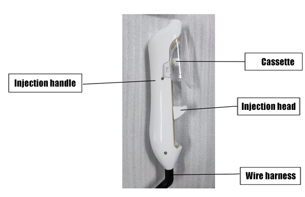
It consists of a host, injection handle (including handle shell, card holder, wiring harness), foot switch, power adapter and embedded software.
Model and specification
YSG-ZS-01
Scope of application
This product is used in conjunction with disposable sterile syringes and disposable sterile injection needles that have obtained medical device registration certificates. It is operated by trained medical personnel in medical institutions and is used for quantitative control of sodium hyaluronate injection into the dermis of patients' faces.
Contraindications
1. Patients who are allergic to drugs or have severe adverse reactions;
2. Emotionally unstable or unwilling to accept;
3. Psychiatric patients whose condition cannot be controlled;
4. Patients with a history of improper medication or suicidal thoughts;
5. Patients with acute diseases;
6. Pregnant women and young children;
Product performance
1. Injection accuracy: The deviation between the actual injection dose and the set dose of the syringe auxiliary propulsion device should be within the range of ±5%
2. Negative pressure intensity: Negative pressure gears are divided into: 1st gear, 2nd gear, 3rd gear, 4th gear, 5th gear, 6th gear, 7th gear, 8th gear, 9th gear, 10th gear.
3. Injection speed
The injection gears are divided into 3 gears: slow, normal, and fast. The corresponding propulsion speeds are shown in Table 2.
4. Infusion function
4.1 Injection mode
The injection mode is divided into: automatic induction, automatic single, single, and continuous. 2
4.2 Injection specifications
Injection specifications are divided into: 0.8/1ml, 1.5/3ml, 2/3ml, 2.5/3ml, 3/3ml, 4/5ml, 5/5ml. Specific descriptions are as follows:
Injection Specification Description List
| Injection specifications | Syringe specifications | Injection dose | Description |
| 0.8/1ml | 1ml | 0.8ml | Indicates that a syringe with a capacity of 1ml draws in 0.8ml of liquid |
| 1.5/3ml | 3ml | 1.5ml | Indicates that a 3ml syringe aspirates 1.5ml of liquid |
| 2/3ml | 2ml | Indicates that a 3ml syringe aspirates 2ml of liquid | |
| 2.5/3ml | 2.5ml | Indicates that a 3ml syringe aspirates 2.5ml of liquid | |
| 3/3ml | 3ml | Indicates that a 3ml syringe aspirates 3ml of liquid | |
| 4/5ml | 5ml | 4ml | Indicates that a 5ml syringe draws in 4ml of liquid |
| 5/5ml | 5ml | Indicates that a 5ml syringe draws in 5ml of liquid |
4.3 Number of injections
The number of injections can be set from 10 to 140 times, with a step of 10.
4.4 Storage function
The device has 4 storage buttons, which can store 4 groups of commonly used parameters. After starting up, it enters the standby display interface.
The interface displays the parameter information when the device was last shut down.
4.5 Prompt function
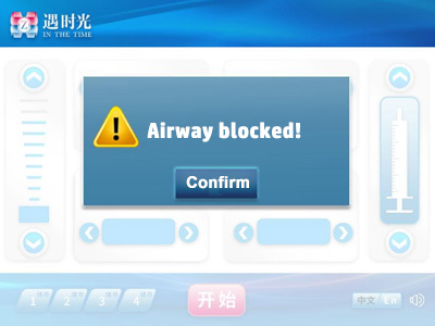
4.5.1 Gas line blockage: When gas line blockage occurs, the display screen jumps to the "Gas line blockage" prompt interface, the working buzzer sounds once, the prompt light flashes yellow once, and the device does not work;
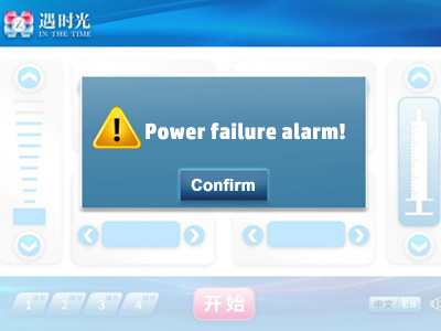
4.5.2 Power failure alarm: When the device is abnormally powered off, the display screen jumps to the "Power failure alarm" prompt interface, the working buzzer sounds once per second, the prompt light flashes red once for 3 minutes, and the device does not work;
4.5.3 Motor stalling: When the motor stalls, the display screen jumps to the "Motor stalling" prompt interface, the buzzer sounds once, the prompt light flashes yellow once, and the device does not work;
4.5.4 Insufficient negative pressure: When the device has insufficient negative pressure, the display screen jumps to the "Insufficient negative pressure" prompt interface, the buzzer sounds once, the prompt light flashes yellow once, and the device does not work.
4.6 Noise
The noise should be lower than 60dB(A) during normal operation.
Normal working conditions
1. Ambient temperature (5-40)℃. If the device is moved from a low temperature area to an operating temperature area, it should be placed in the packaging for at least 4 hours before opening the packaging and starting the device.
2. Relative humidity: 20%-90%.
Electrical safety
1. Classification by electric shock protection type: Class II;
2. Classification by safety level when used with flammable anesthetic gas mixed with air or flammable anesthetic gas mixed with oxygen or nitrous oxide: Not applicable;
3. Rated voltage and frequency: power adapter input: AC 220V 50Hz, power adapter output: DC12V 5A;
4. Rated input power: 90VA;
Software
Software name: Syringe auxiliary propulsion device control software
Software model specification: ZS-R
Software release version number: V1.2
Product installation and usage instructions
1. Product structure diagram
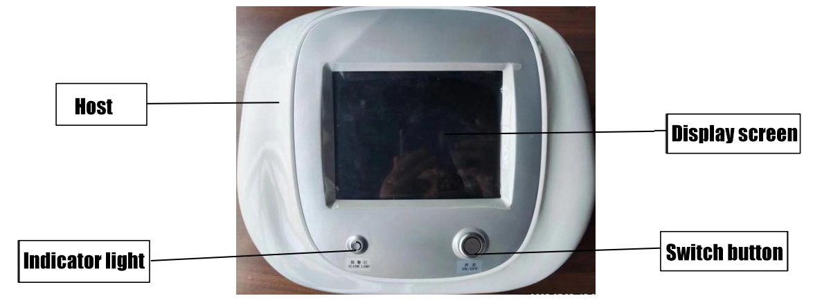
Host diagram
 |
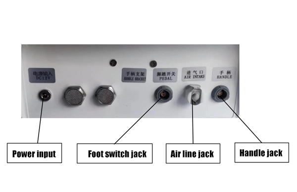 |
| Injection handle diagram | Jack Diagram |
2. Description of each component of the product
Host function: Displays negative pressure intensity, injection speed, injection mode, injection specifications, injection times, storage function and infusion function. Each function mode can be controlled by the adjustment button on the display screen;
Injection handle function: Used with syringe and injection needle;
Foot switch function: Used with injection mode;
Power adapter function: Power input and output;
Embedded software function: Controls the negative pressure intensity, injection speed, injection mode, injection specifications, injection times, storage function and infusion function of the product.
3. Product Installation
3.1 Fixing the syringe
This product can be placed directly on the table for use. The fixing height should be about 0.5m above the bed and about 1.2m above the ground.
3.2 Installation of syringe and injection needle
When using 1ml/3ml/5ml syringe, the installation steps are as follows:
(1)Install the corresponding specification holder to the handle body;
(2)The syringe sucks the corresponding dose of liquid;
(3)Install the injection needle to the syringe, push the syringe piston, and exhaust the air;
(4)Install the syringe and injection needle as a whole to the handle body;
3.3 Connection of air pipe and filter tube
(1)Connect the handle air pipe and filter tube with a metal Luer connector;
(2)Insert the other end of the filter tube into the exhaust hole of the nine-needle needle, suck the injection liquid with the syringe and connect it with the nine-needle needle;
(3)Then clamp the syringe and needle in the working position of the handle. (Note that before clamping the syringe, adjust the position of the handle push rod first. After the syringe is clamped, adjust the push rod position to exhaust the air in the syringe)
3.4 Schematic diagram of injection handle connection
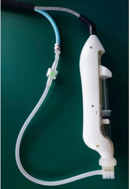
Injection handle connection diagram
4. Instructions for use
4.1 Power on
Press the power button to start the power on operation. After power on, run the self-test program. If there is a prompt message, enter the corresponding prompt interface. If there is no prompt message, directly enter the standby display interface. The standby interface displays the information when the power was last turned off;
4.2 Operation method
4.2.1 Standby display interface

4.2.2 Injection speed
Press the left and right arrows in the injection speed display area of the standby interface to set the injection speed. After setting, it will take effect immediately and automatically save as the parameters of the current storage block.
Speed gear: Slow, normal, and fast speed gears are optional.
4.2.3 Negative pressure intensity setting
The negative pressure intensity can be set by touching the up and down buttons, and the icon and number are indicated synchronously. The maximum negative pressure intensity is 10 levels, and the minimum negative pressure intensity is 1 level. After setting, it will take effect immediately and automatically save as the parameters of the current storage block.
4.2.4 Injection mode setting
Press the left and right arrows in the injection mode display area of the standby interface to set the injection mode. After setting, it will take effect immediately and automatically save as the parameters of the current storage block.
Automatic sensing: After selecting the parameters to start the device, the injection will be automatically completed according to the set parameters after the skin is sensed.
Automatic single: After selecting the parameters to start the device, it will automatically inject once when the skin is sensed and there is a foot signal. If there is always a foot signal, an injection will be performed each time the skin is sensed.
Single: After selecting the parameters to start the device, it will automatically inject once when the skin is sensed and there is a pedal signal. If there is always a pedal signal and the device does not release and then step on the action, it will not perform the next injection.
Continuous: After selecting the parameters to start the device, it will sense the skin and inject continuously when there is a pedal signal.
The injection will stop when the pedal signal disappears.
4.2.5 Injection Specifications
Press the left or right arrows in the injection specification display area of the standby interface to set the injection dosage. Once set, it will take effect immediately and automatically saved as the parameters of the current storage block.
(1)0.8/1ml: means to select a 1ml syringe and inhale the liquid to the 0.8ml mark;
(2)1.5/3ml: means to select a 3ml syringe and inhale the liquid to the 1.5ml mark;
(3)2/3ml: means to select a 3ml syringe and inhale the liquid to the 2ml mark;
(4)2.5/3ml: means to select a 3ml syringe and inhale the liquid to the 2.5ml mark;
(5)3/3ml: means to select a 3ml syringe and inhale the liquid to the 3ml mark;
(6)4/5ml: means to select a 5ml syringe and inhale the liquid to the 4ml mark;
(7)5/5ml: means to select a 5ml syringe and inhale the liquid to the 5ml mark;
4.2.6 Injection times
Press the left or right arrows in the injection times display area on the standby interface to set the injection times. Once set, it will take effect immediately and automatically save as the parameters of the current storage block.
Injection times: 10/20/30/40/50/60/70/80/90/100/110/120/130/140, a total of 14 times are available.
When adjusting the injection times, the device calculates the single injection volume in real time according to the selected injection specifications and the currently selected injection times.
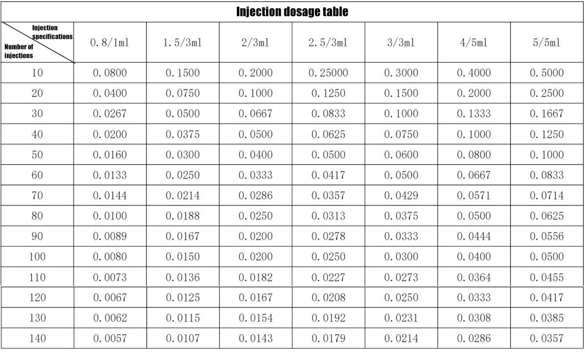
4.2.7 Injection accuracy
Press the left or right arrows in the injection dose display area on the standby interface to set the injection dose. Once set, it will take effect immediately and automatically save as the parameters of the current storage block.
The injection dose is calculated according to the currently selected syringe specifications and the step value of the injection times.
The reference injection dose table is as follows:

4.2.8 Propulsion device position control
Press and hold the up and down arrows to control the movement of the propulsion device, and release to stop immediately.
4.2.9 Storage function
The device has 4 storage buttons, which can store 4 groups of commonly used parameters. After starting up, it enters the standby display interface, and the interface displays the parameter information when the device was last shut down.
4.2.10 Turn the key tone on and off
Press the speaker button to switch the key prompt tone on and off.
4.2.11 Language selection
The device has a Chinese and English switch button, which can switch the display of Chinese or English interface.
4.2.12 Start and stop control
Press repeatedly to switch back and forth between start and stop.
4.2.13 Shutdown
After use, press the switch button to shut down.
4.3 Fault Indicators and Tips
4.3.1 Gas path blockage
If the device is running automatically or the position of the propulsion device is adjusted manually, if a stall occurs, the motor will stop rotating immediately and stop after running in the opposite direction for about 1mm. At the same time, the interface shown above will be entered. Press the "Confirm" button in the white square area in the middle of the screen to enter the standby display interface. The buzzer will sound once and the indicator light will flash yellow once.
4.3.2 Power-off prompt
If an abnormal power outage occurs during the operation of the device or the shutdown button is pressed, the device will resume power supply within 3 minutes. At this time, the interface shown in the figure above will be entered to remind the operator that an abnormal power outage occurred during the last injection. Press the "Confirm" button in the white square area in the middle of the screen to enter the standby display interface. When an abnormal power outage occurs, the device immediately uses the power stored in the backup capacitor to open the solenoid valve and release the negative pressure of the negative pressure system, so that the injection needle can be separated from the skin normally. After an abnormal power outage occurs, the buzzer sounds once per second and the warning light flashes red once for 3 minutes;
4.3.3 Motor stall
If the device stalls during automatic operation or when the propulsion device is manually adjusted, the motor will stop rotating immediately and stop after running in the opposite direction for about 1mm. At the same time, the interface shown above will be entered. Press the "Confirm" button in the white square area in the middle of the screen to enter the standby display interface. The buzzer will sound once and the indicator light will flash yellow once.
 |
 |
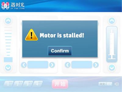 |
| Airway blocked | Power off reminder | Motor stall |
4.3.5 Injection reminder
After each injection, the buzzer will sound once as a reminder, and after the injection is completed, the buzzer will sound twice as a reminder.
Common troubleshooting methods
| Common fault handling | ||||
| Serial number | Fault phenomenon | Fault type | Fault cause | Maintenance suggestion |
| 1 | Incorrect injection dose | Syringe specifications | Not using the syringe recommended by our company | Use the syringe recommended by our company |
| 2 | Configuration does not match the actual | The syringe specifications selected through the screen are inconsistent with the actual syringe used | Check to keep consistent | |
| 3 | Mechanical error | Mechanical error caused by long-term operation | Please contact our company | |
| 4 | Syringe does not advance | Negative pressure system abnormality | Gas circuit connection leaks | Reconnect gas circuit |
| 5 | Needle is not close to the skin | Standardized use | ||
| 6 | Motor stall prompt | Motor stall | Propulsion device runs to the maximum position | Let the propulsion device run in the specified range |
| 7 | Handle line is not connected normally | Reconnect handle line | ||
| 8 | Motor or encoder damaged | Please contact our company | ||
Product maintenance and care methods
1. Maintenance
If you find any signs of damage to the function of this product, do not continue to use it, please contact our maintenance engineer.
Every 12 months or after each maintenance, a qualified person must conduct a comprehensive inspection of the equipment, including a functional safety inspection.
All inspections that require opening this product must be conducted by qualified maintenance personnel.
Safety and maintenance inspections can also be conducted by our personnel.
2. Cleaning and disinfection
After each use, wipe the surface of the product and its accessories with a clean cloth, then wipe the surface with 75% medical alcohol 2-3 times for disinfection, and dry it naturally or with a clean, dry cloth.
3. Storage and transportation conditions and methods
a. Do not throw or drop during loading and unloading; avoid severe vibration during transportation;
b. During transportation, it should be placed upward, afraid of moisture, carefully placed, and prevent heavy pressure;
c. It should be stored in a temperature range of -20℃~+55℃, relative humidity not exceeding 85%, no corrosive gas, cool, dry, well-ventilated and clean environment.
Warnings and Precautions
1. Warning
Warning: If the equipment is not inspected and maintained regularly, it may cause the equipment to fail and may endanger human health.
Warning: Before cleaning this product, the power must be turned off and the AC power must be disconnected.
Warning: Do not modify this equipment without the manufacturer's authorization.
2. Precautions
2.1 Please read the instructions before use and operate strictly in accordance with the instructions.
2.2 The product must be used by personnel who have undergone professional training and passed the assessment.
2.3 During use, closely observe the patient's reaction and adjust the parameters in time to achieve the best treatment effect.
2.4 Patients are not allowed to plug and unplug the pipeline without authorization.
2.5 Avoid sharing the socket with high-power surgical equipment or being too close to it, and avoid using this instrument in a strong electric field or strong magnetic field environment.
2.6 The syringe auxiliary propulsion device should not be used close to or stacked with other equipment to avoid mutual interference and affect the use.
2.7 Use the accessories and power adapter provided by the manufacturer. The use of accessories and power adapters other than those specified may increase the emission of the instrument or reduce the immunity.
2.8 When connecting the injection handle, check whether the injection handle and the filter tube are firmly connected.
2.9 The scrapping of this product and its accessories at the end of their service life should comply with local laws and regulations. If improperly handled, the electronic components in this product and its accessories will cause pollution to the environment.
Accessories and ordering information
The injection needles and syringes used with the product must have a medical device product registration certificate. You can purchase them directly from the syringe manufacturer or through our company.
| Name | Specifications |
| Disposable sterile syringe | 1ml |
| Disposable sterile syringe | 3ml |
| Disposable sterile syringe | 5ml |
| Disposable sterile injection needle | 9P |
Parts List
| Name | Quantity | Unit |
| Host | 1 | Unit |
| Power Cord | 1 | Root |
| Adapter | 1 | pcs |
| Foot switch | 1 | pcs |
| Injection handle | 1 | pcs |
| Injection handle bracket | 1 | Set |
| Instruction manual | 1 | This |
Logo Graphic Explanation
Circuit diagram, component list
If customers really need information such as the circuit diagram and component list of this product, they can contact the manufacturer.
Product after-sales service and commitment
Our after-sales service policy is: The warranty period is within one year after payment, and we provide free video guidance and accessories services, and the postage needs to be paid by the buyer; after more than one year, the buyer needs to pay for the accessories and postage.
Electromagnetic compatibility information
Note:
● The syringe-assisted propulsion device complies with the relevant requirements of the electromagnetic compatibility of the YY 9706.102-2021 standard.
● The user should install and use it according to the electromagnetic compatibility information provided in the random documents.
● Portable and mobile RF communication equipment may affect the performance of the syringe-assisted propulsion device. Avoid strong electromagnetic interference when using it, such as near mobile phones, microwave ovens, etc.
● The guidelines and manufacturer's statements are detailed in the attachment.
Warning:
● The syringe-assisted propulsion device should not be used close to or stacked with other equipment. If it must be used close to or stacked,
it should be observed and verified that it can operate normally in the configuration it is used in;
● Except for cables, transducers and other accessories sold by the manufacturer of the syringe-assisted propulsion device as spare parts for internal components, the use of accessories, transducers or cables other than those specified in the regulations with the syringe-assisted propulsion device may result in an increase in the emission of the syringe-assisted propulsion device or a decrease in immunity.
| Cable name | Cable length (m) | Is it shielded |
| Power cord | 1.5 | No |
| Power adapter | 1.5 | No |
| Handle connection cable | 1.5 | No |
| Foot switch connection cable | 2.0 | No |
RELATED PRODUCTS
MESSAGE
Shandong YSG Technology Development Co., Ltd.
Address:Room 1001, Building B, shounuo City Light, Huaiyin District, Jinan City, Shandong Province
Tel: +86-18259383887
WhatsApp:+86-18259383887
E-mail: YXX@ysg123.com.cn